Presentation of the project
Contract:
TE 148 from 06.06.2022
Submission code:
PN-III-P1-1.1-TE-2021-0949
Contract duration:
24 months
Contractor:
National Institute for Laser, Plasma and Radiation Physics INFLPR
Contracting authority:
Executiv Unit for Financing Higher Education, Research, Development and Innovation UEFISCDI
THz scanning interferometer with enhanced resolution using amplitude control
Interferometru de scanare în domeniul THz cu rezoluție îmbunătățită utilizând controlul amplitudinii
Acronym: THEZSERACT
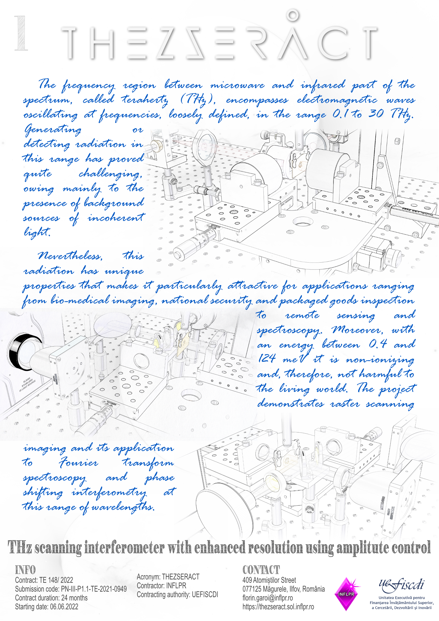
The frequency region between microwave and infrared part of the spectrum, called terahertz (THz), encompasses electromagnetic waves oscillating at frequencies, loosely defined, in the range 0.1 to 30 THz. Generating or detecting radiation in this range has proved quite challenging, owing mainly to the presence of background sources of incoherent light. Nevertheless, this radiation has unique properties that makes it particularly attractive for applications ranging from bio-medical imaging, national security and packaged goods inspection to remote sensing and spectroscopy. Moreover, with an energy between 0.4 and 124 meV it is non-ionizing and, therefore, not harmful to the living world.
The investigation of this electromagnetic region can be dated to the end of the 19th century, shortly after Heinrich Rudolf Hertz's pioneering work on electromagnetic waves. Today, the most accessible technique for recording or measuring data in this spectral range, except time-domain spectroscopy/imaging, is the single-pixel imaging (SPI). In this view, a given THz scene may be achieved either by using raster scanning (RS) or multiplexing (MS) techniques.
With this proposal we intend to use RS or/and MS in order to improve the resolution of imaging at submillimeter radiation, and demonstrate its application to Fourier transform spectroscopy (FTS) and phase shifting interferometry (PSI) at these wavelengths range. This is because both FTS and PSI are readily applicable to SPI and interferometry is a reliable and non-invasive testing tool.
Regiunea spectrală între microunde și infraroșu, numită terahertz (THz), cuprinde unde electromagnetice care oscilează la frecvențe cuprinse în intervalul 0,1 – 30 THz. Generarea sau detectarea radiației în domeniul THz s-a dovedit a fi destul de dificilă, în special din cauza prezenței surselor incoerente de fundal. Totuși, această radiație are proprietăți unice care o fac deosebit de atractivă pentru aplicații care variiază de la imagistică bio-medicală, securitate și inspecția mărfurilor până la teledetecție și spectroscopie. Mai mult decât atât, cu o energie între 0,4 și 124 meV este neionizantă și, prin urmare, nu dăunează lumii vii.
Investigarea acestei regiuni electromagnetice poate fi datată la sfârșitul secolului al XIX-lea, la scurt timp după lucrările de pionierat ale lui Heinrich Rudolf Hertz asupra undelor electromagnetice. Astăzi, cea mai accesibilă tehnică pentru înregistrarea sau măsurarea datelor în acest interval spectral, cu excepția spectroscopiei/imagisticii în domeniul temporal, este imagistica cu un singur pixel (SPI). Din acest punct de vedere, o anumită scenă THz poate fi obținută fie folosind tehnica de scanare raster (RS) sau cea de multiplexare (MS).
Prin această propunere, intenționăm utilizarea RS sau/și MS pentru a îmbunătăți rezoluția imagisticii la radiații submillimetrice și demonstrarea aplicării acesteia la spectroscopia cu transformată Fourier (FTS) și interferometria cu decalare de fază (PSI) la aceste lungimi de undă. Atât FTS cât și PSI sunt direct aplicabile la SPI, iar interferometria este un instrument de testare fiabil și non-invaziv.
Objectives
- Improving the resolution of THz imaging with the use of raster scanning technique
- Designing and building an interferometric setup working at THz frequencies
- Achieving spectra and profiles of samples by implementing Fourier transform spectroscopy and phase-shifting methods at THz domain
Phases
- Imaging architecture and concept of THz interferometric setup
- Development of functions of the THz interferometer by Fourier Transform Spectroscopy and Phase Shifting Interferometry
- Evaluation of the breadboard THz imaging interferometer
Team

Florin Garoi
Research Scientist Project Coordinator

Mihaela Bojan
Research Scientist Team Member

Cristian Udrea
Research Scientist Team Member

Petronela Garoi
Research Scientist Team Member

Ionuț-Relu Andrei
Research Scientist Team Member

Iuliana Urzică
Research Scientist Team Member
Results
Publications
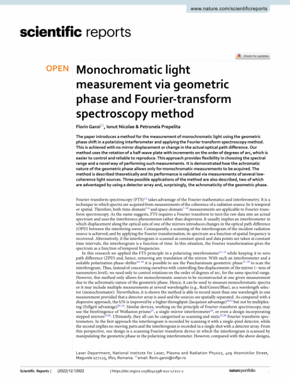
- Garoi F., Nicolae I. & Prepelita P. Monochromatic light measurement via geometric phase and Fourier-transform spectroscopy method. Sci Rep 12, 12922 (2022). https://doi.org/10.1038/s41598-022-17211-1
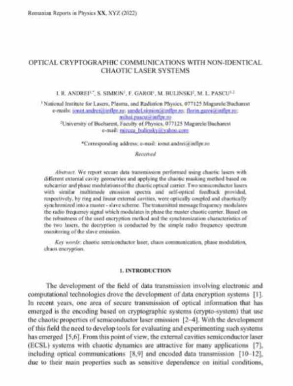
- I. R. Andrei, S. Simion, F. Garoi, M. Bulinski, M. L. Pascu. Otpical cryptographic communications with non-identical chaotic laser systems. Rom Rep Phys 75 (3), art. no. 408 (2023). 10.59277/RomRepPhys.2023.75.408
Patents
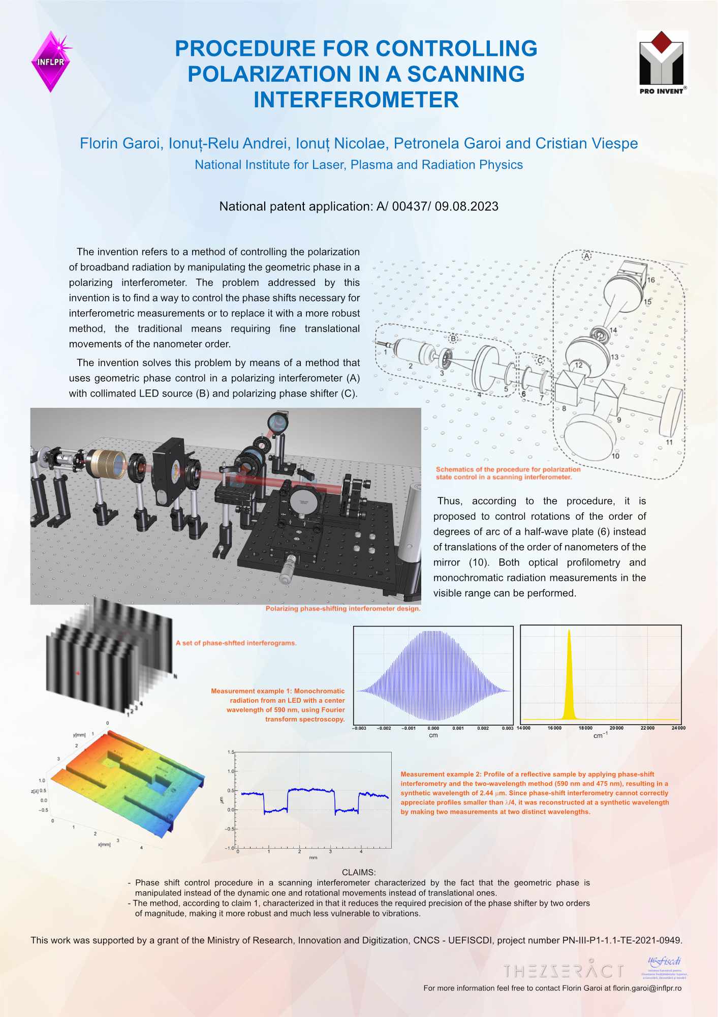
- Garoi Florin, Andrei Ionuț-Relu, Nicolae Ionuț, Garoi Petronela & Viespe Cristian, Procedeu de control al stării de polarizare într-un interferometru de scanare, OSIM patent application no. A/ 00437/ 09.08.2023 - Submission pending GRAND PRIZE of the Romanian Inventors Forum at Pro Invent 2023
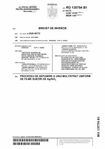
- Garoi Petronela, Viespe Cristian, Garoi Florin, Valentin Craciun, Procedeu de depunere a unui multistrat unifor de filme subtiri de Ag/SiO2, OSIM patent no. RO 135754 B1/ 30.08.2023 - Published
Conferences
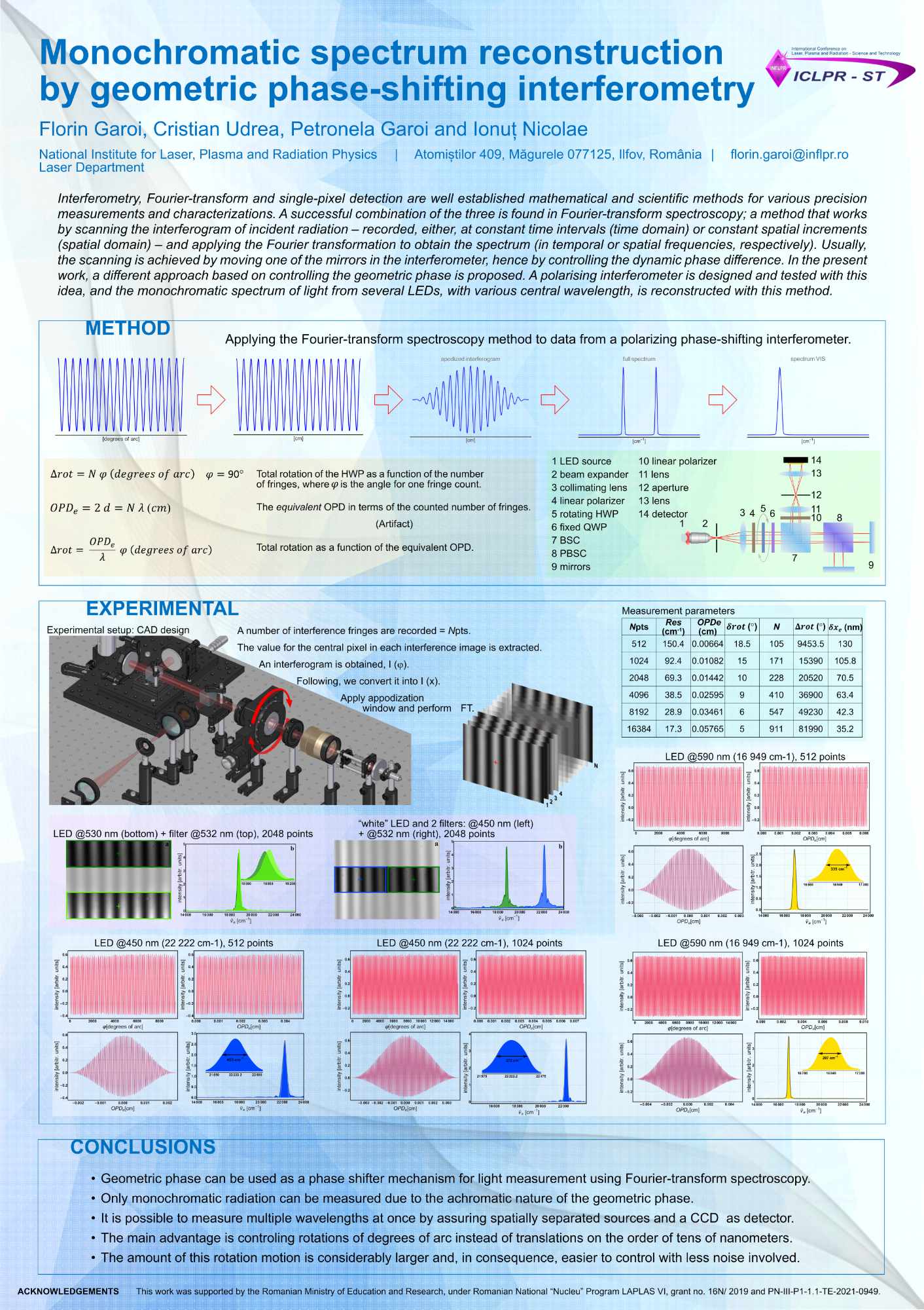
- Garoi F., Udrea C., Garoi P. & Nicolae I. Monochromatic spectrum reconstruction by geometric phase-shifting interferometry. International Conference on Laser, Plasma and Radiation Technology June 7-10 (2022), Bucharest, Parliament Palace. Poster nr. P2.16
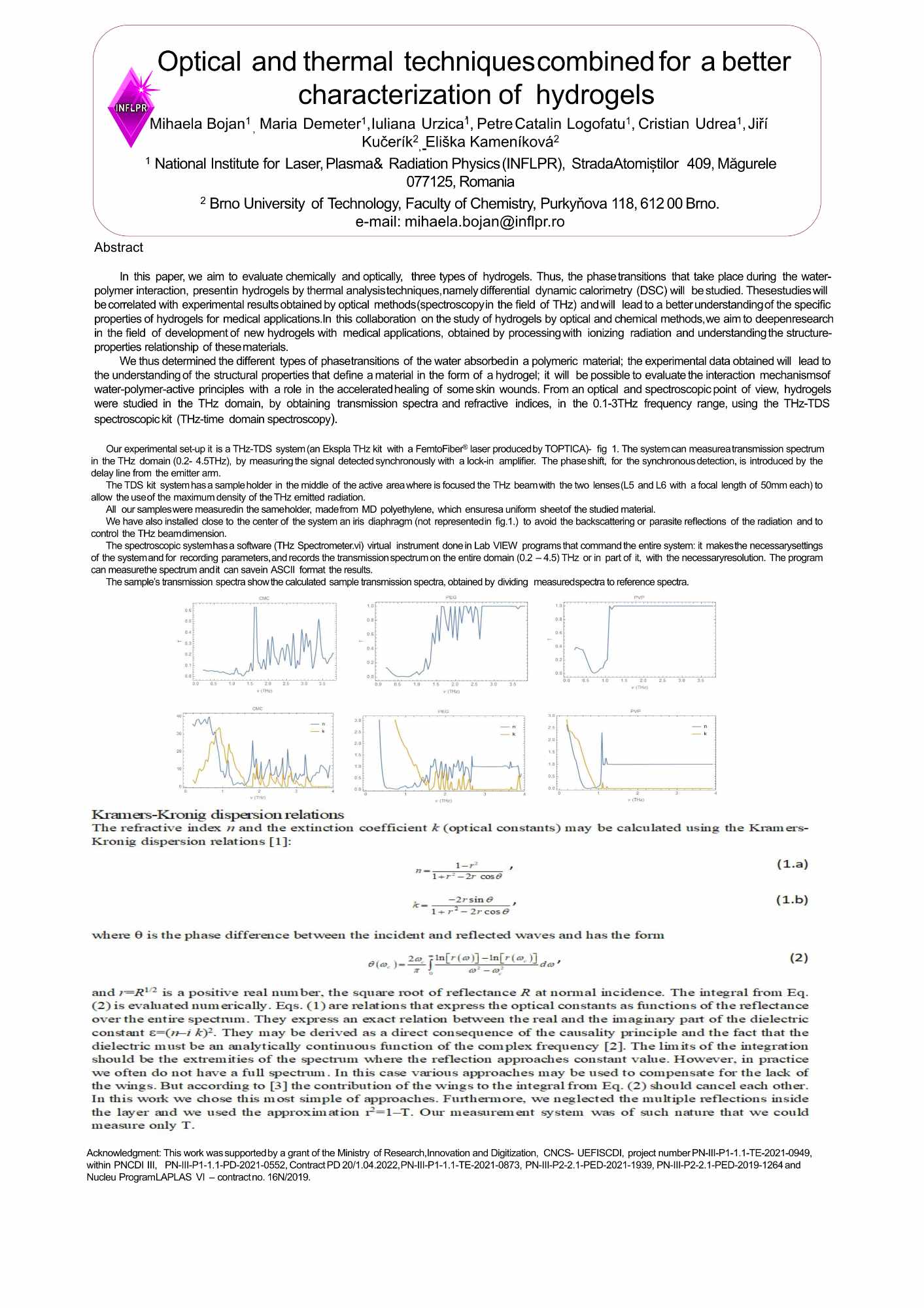
- Bojan, M., Demeter, M.,Urzica, I., Logofatu, P.C., Udrea, C., Kučerík, J., Kameníková, E. Optical and thermal techniques combined for a better characterization of hydrogels. 1st Central and Eastern European Confernce on Physical Chemistry and Materials Science July 26-30 (2022), Split, Croatia. Poster nr. PS1.38
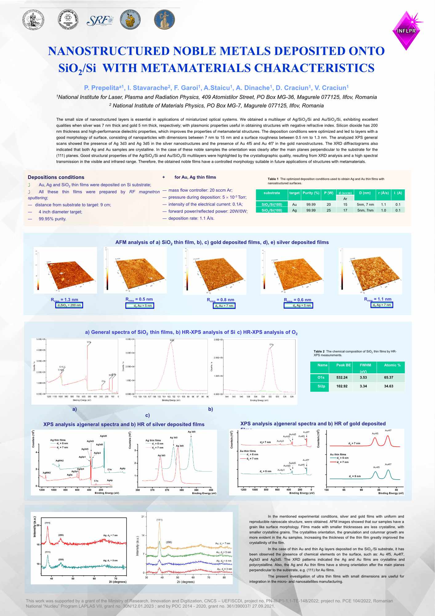
- P. Prepeliță, I. Stăvărache, F. Garoi, A. Staicu, A. Dinache, D. Crăciun, V. Crăciun. Nanostructured noble metals deposited onto SiO2/Si with metamaterials characteristics. 21st International Balkan Workshop on Applied Physics and Materials Science July 11-14 (2023), Constanța, România.
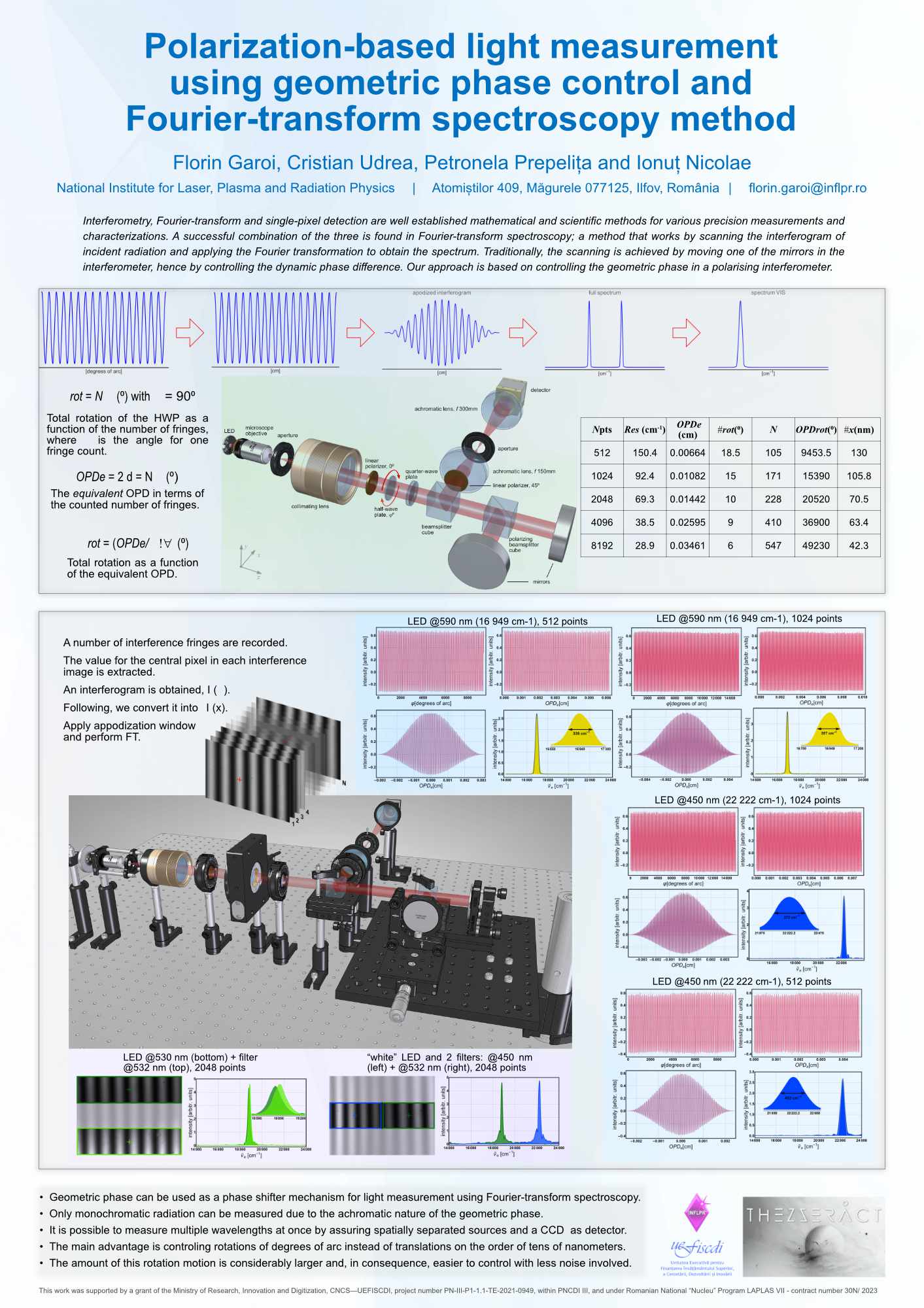
- Garoi, F., Udrea, C., Prepelița, P. & Nicolae, I. Polarization-based light measurement using geometric phase control and Fourier-transform spectroscopy. 21st International Balkan Workshop on Applied Physics and Materials Science July 11-14 (2023), Constanța, România. Poster nr. S2.P16
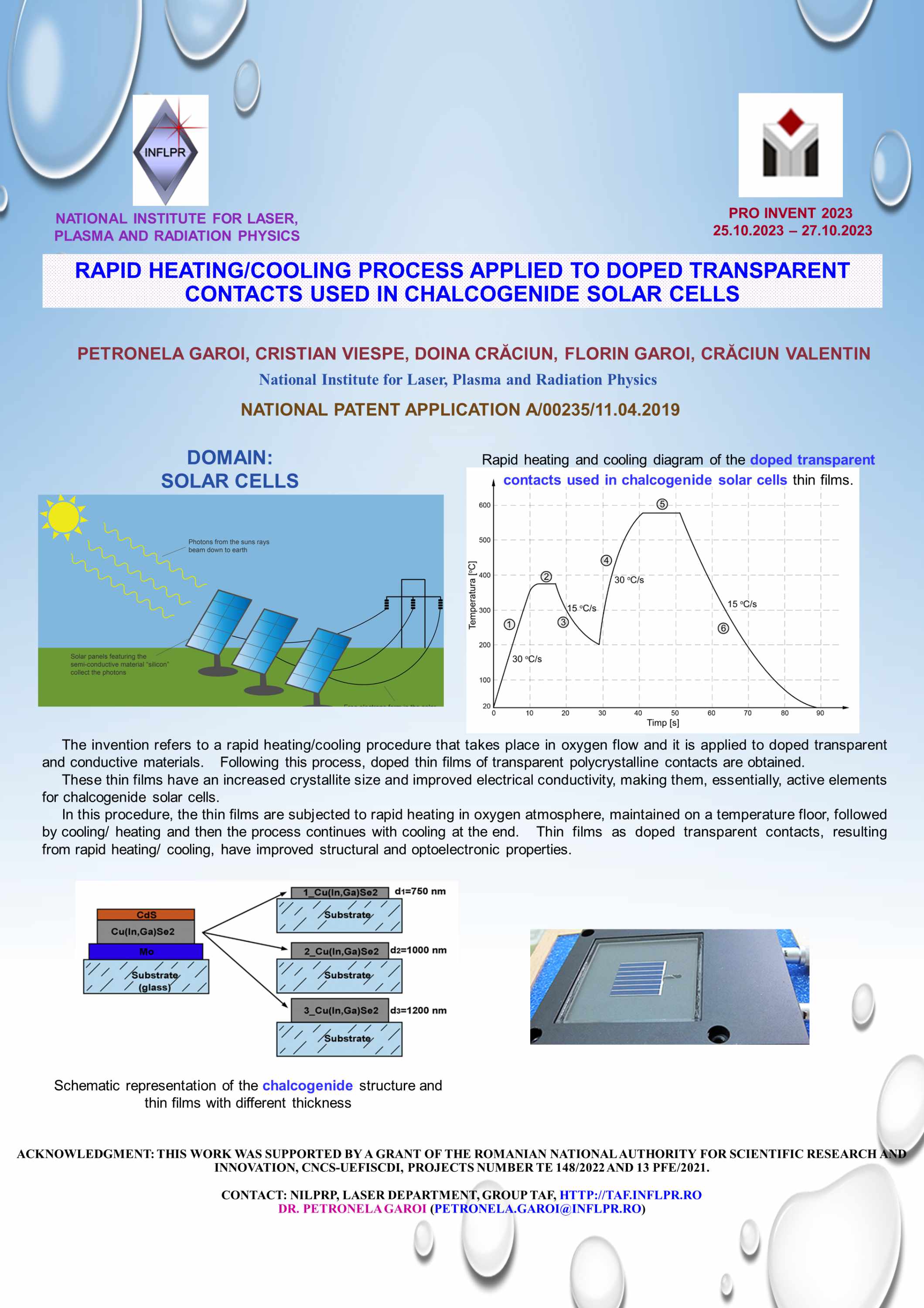
- P. Garoi, C. Viespe, D. Crăciun, F. Garoi, V. Crăciun. Rapid heating/ cooling process applied to doped transparent contacts used in chalcogenide solar cells. Pro Invent 2023 October 25-27 (2023), Cluj, România.
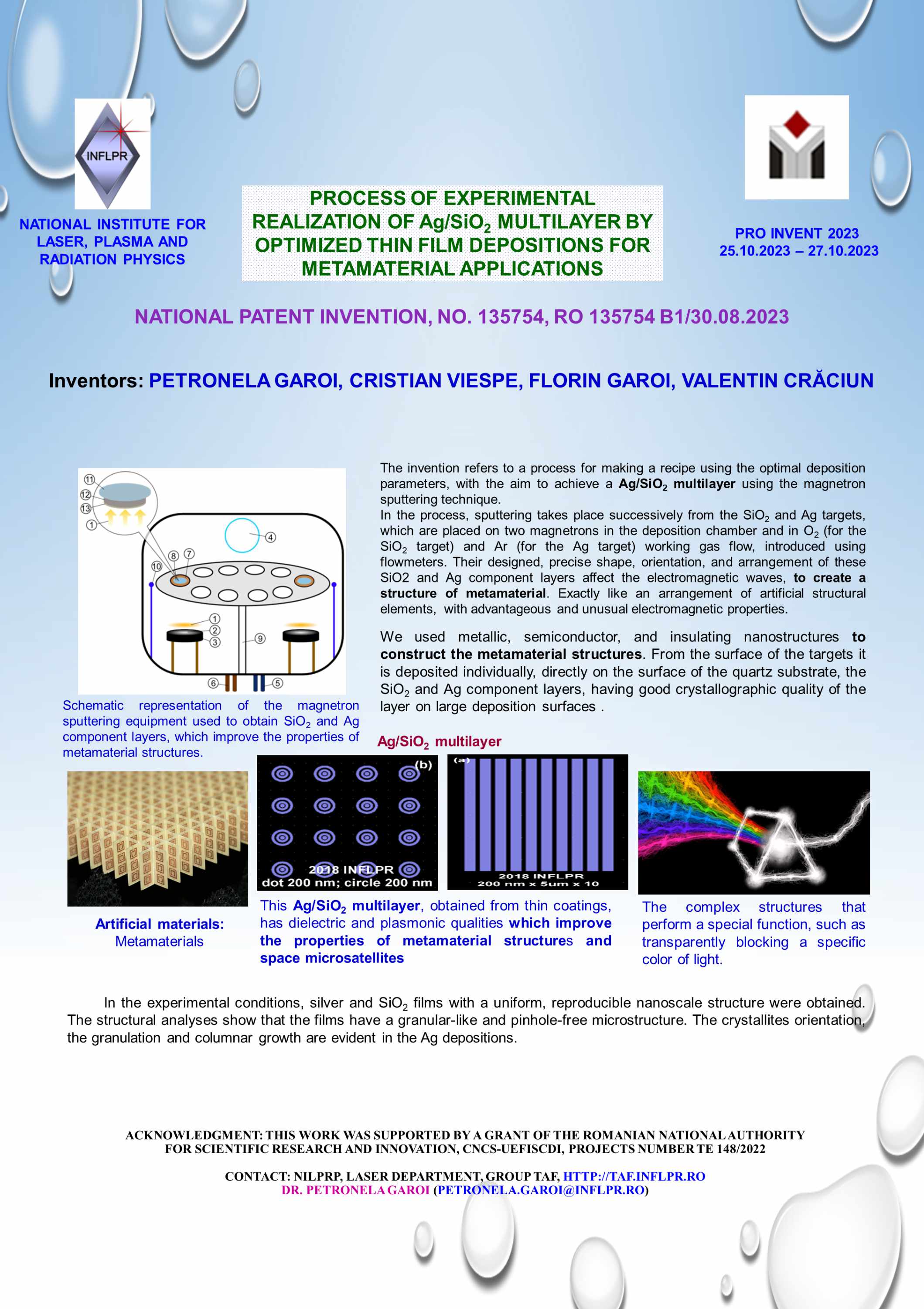
- P. Garoi, C. Viespe, F. Garoi, V. Crăciun. Process of experimental realization of Ag/SiO2 multilayer by optimized thin film depositions for metamaterial applications. Pro Invent 2023 October 25-27 (2023), Cluj, România.
- Garoi F., Andrei I.- R., Nicolae I., Garoi P. & Viespe C. Procedure for controlling polarization in a scanning interferometer. Pro Invent 2023 October 25-27 (2023), Cluj, România.
Reports
[2022] Stage I - Imaging architecture and concept of THz interferometric setup
Raster scan and single-pixel imaging at visible (VIS) range
The spectral domain between microwaves and infrared is called Terahertz, and the electromagnetic waves specific to this domain oscillate at frequencies between 0.1 - 30 THz. Although considerable progress has been made in the development of sources and detectors, the most accessible data recording/measurement technique for this spectral domain is, for now, single pixel detection.
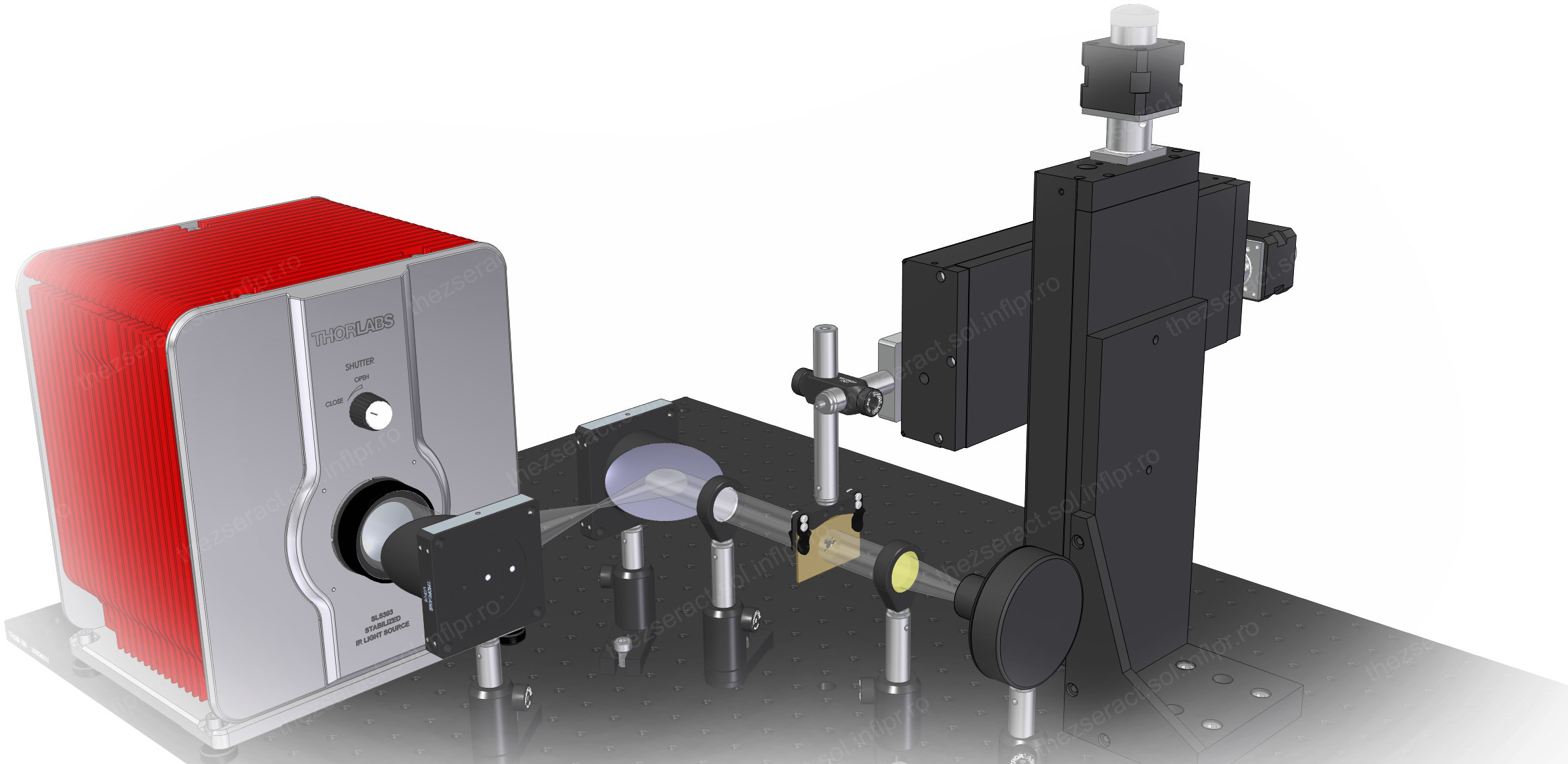
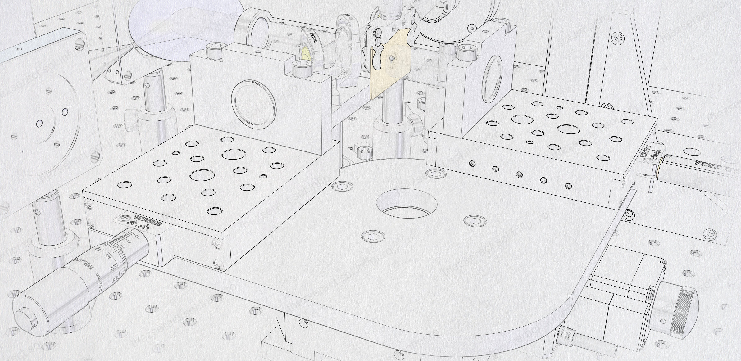
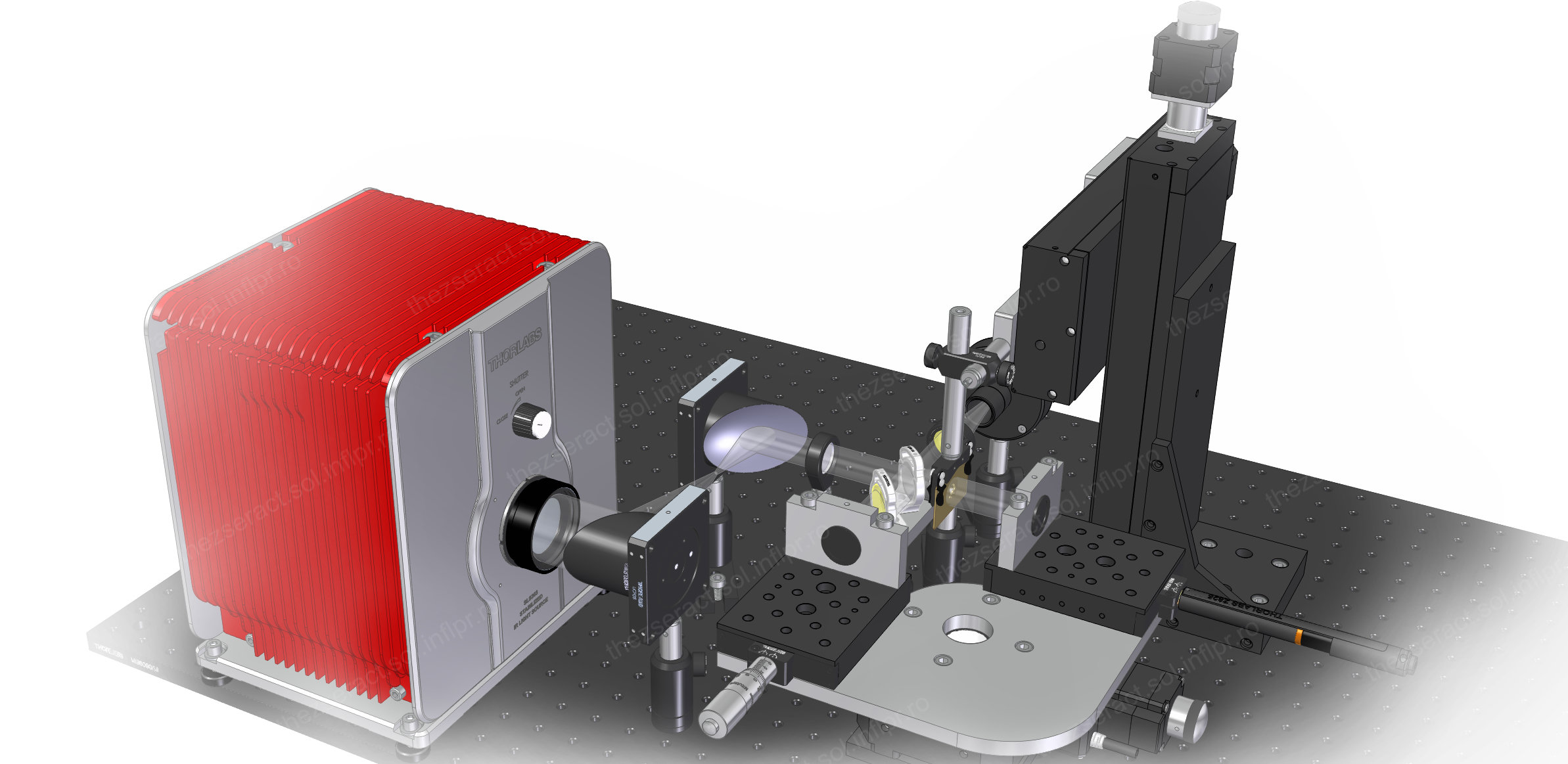
Raster scanning is one method to achieve detection with a single pixel detector. This involves scanning the object pixel by pixel and reconstructing it using computational methods. The first stage involves design/simulation activities to identify an optimal single-pixel imaging setup. It is also taken into account that eventually the experimental setup will have to incorporate a scanning interferometer with spectroscopy and profilometry functions.
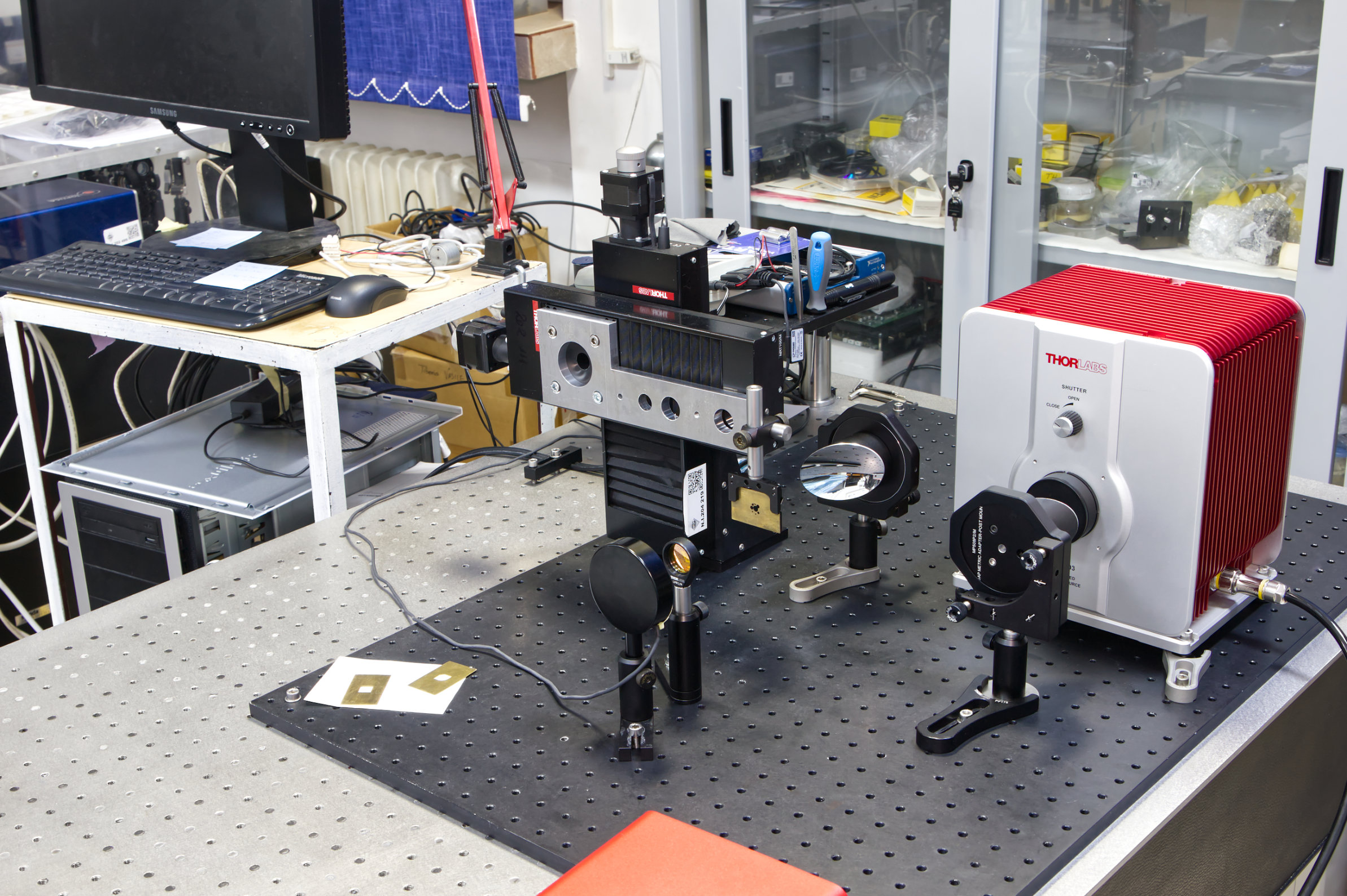
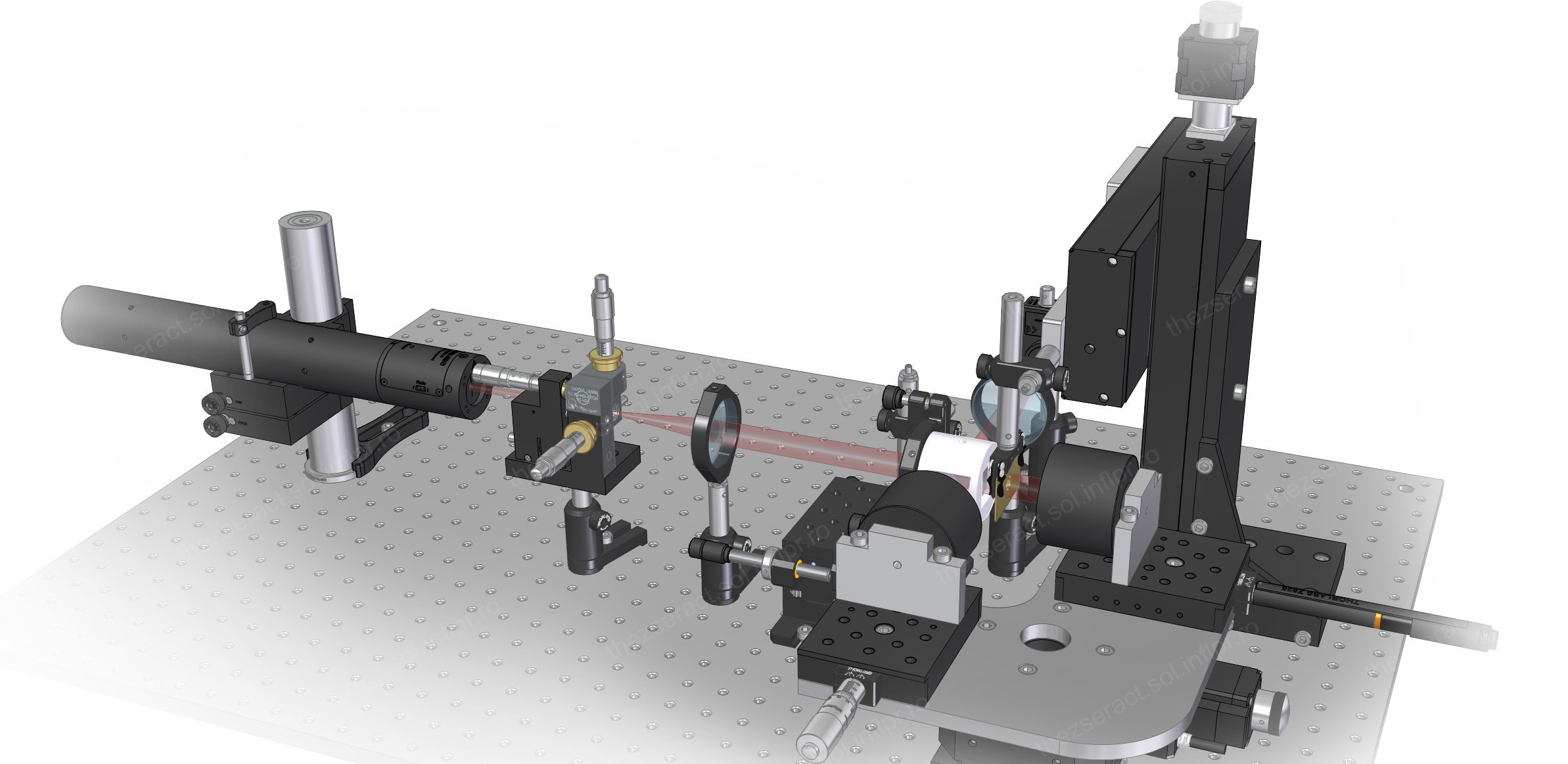
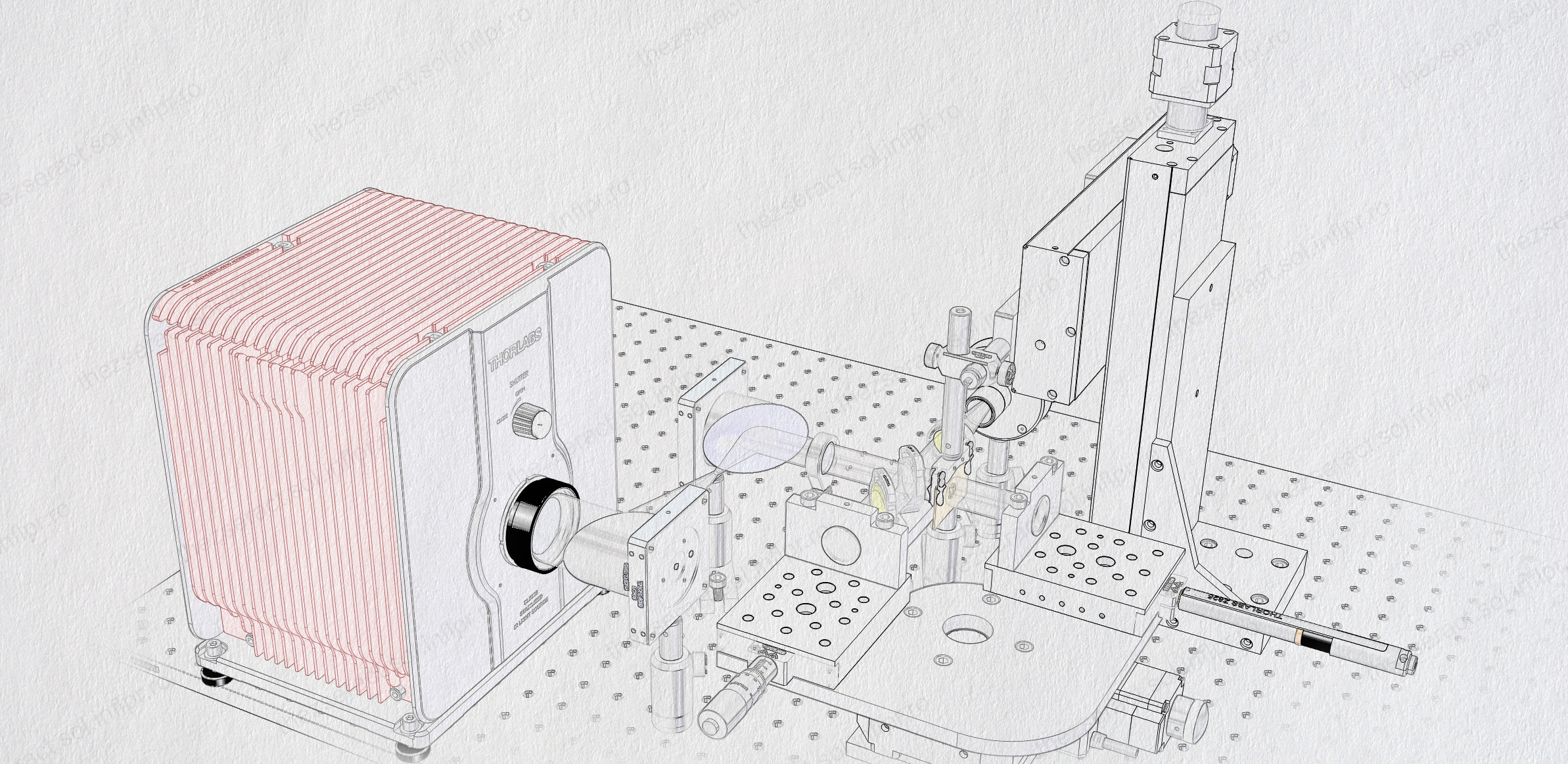
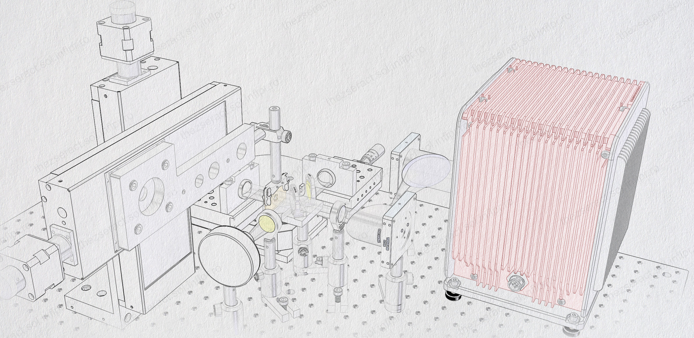
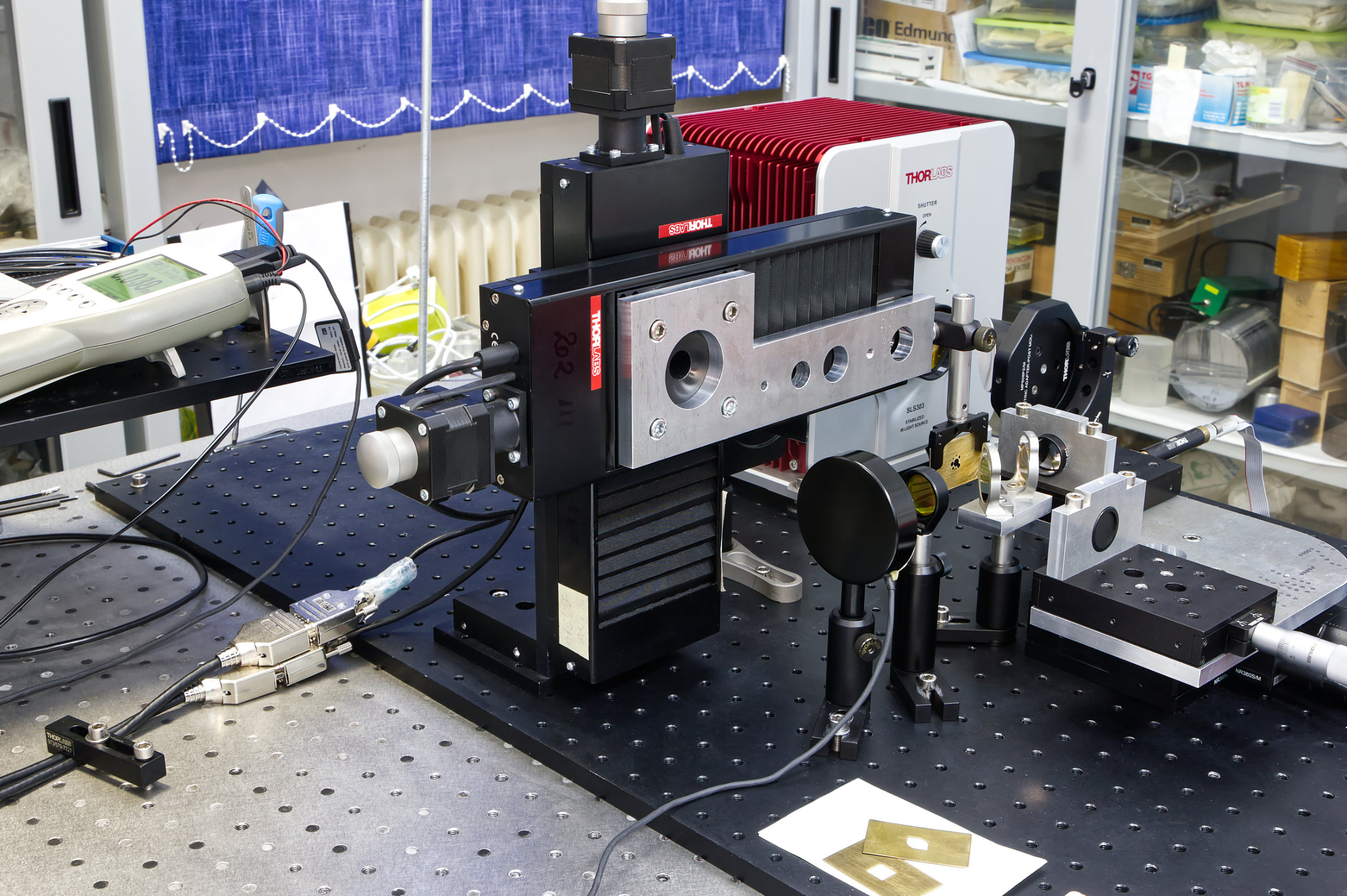
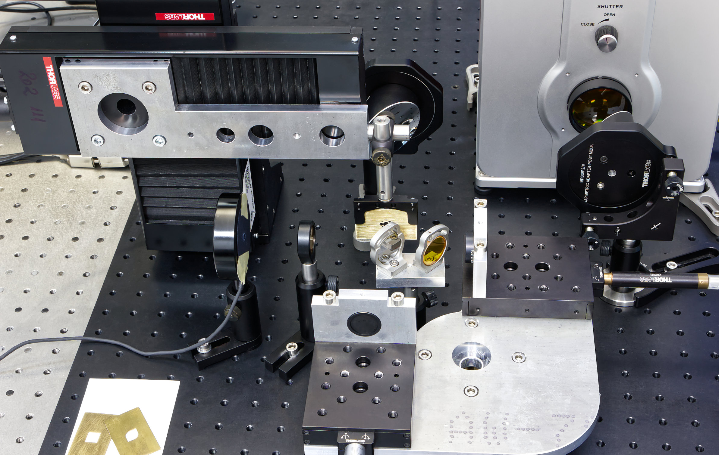
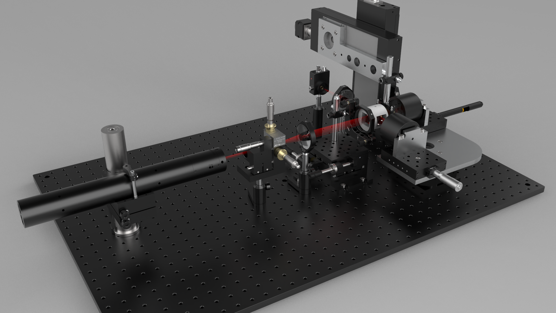
Several CAD simulations of single-pixel optical imaging setups were performed, including a tentative interferometric setup. Given that THz radiation is invisible we performed initial designs/ testing in the visible spectral range, both coherent and broadband/LED radiation. The development of the automation and control system (including the control of the translation tables and the acquisition of the signal from the photodetector) could only be carried out and tested in a visible radiation setup; otherwise, it is not feasible because a working experimental model is needed. Besides, the alignment of some experimental configurations as well as the testing of some concepts is achieved in a much shorter time by initially working with visible radiation. The transition to a THz radiation setup can be easily implemented at a later stage.
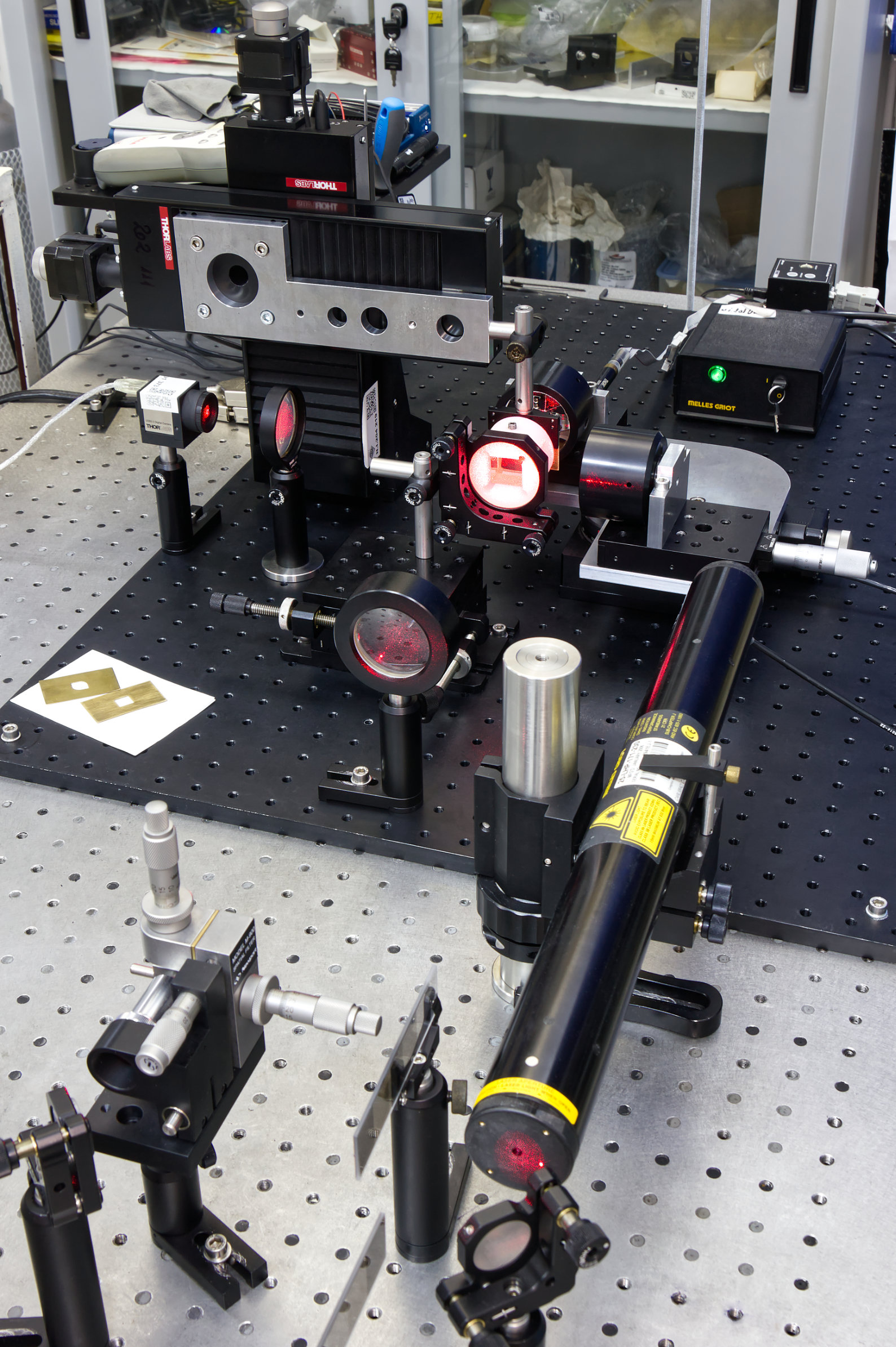
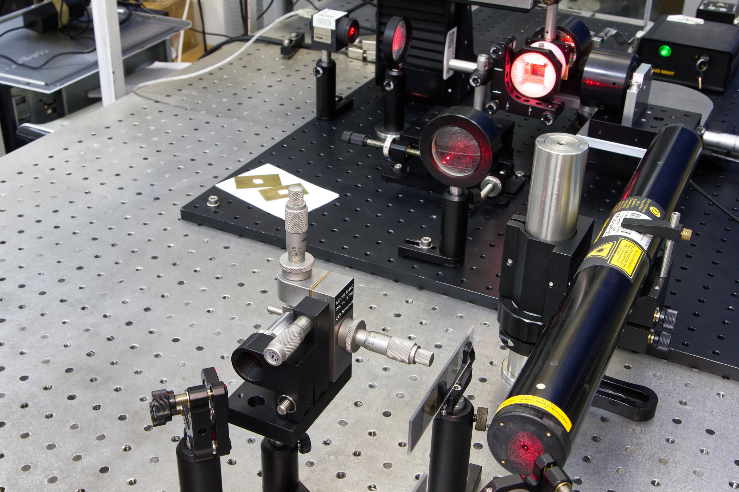
Single-pixel imaging by raster scanning method on an experimental model with coherent radiation from a HeNe laser (λ = 632.8 nm) was tested. At this point, the acquisition was performed by continuous scanning and recordings at constant time intervals. We tested various optical components, scanning speeds and resolutions to determine the optimal conditions for obtaining images of specially designed transmissive samples. Resolutions of 1024px2, 4096px2 and 16384px2, respectively, were achieved.
[2023] Stage II - Development of functions of the THz interferometer by Fourier Transform Spectroscopy and Phase Shifting Interferometry
Single-pixel imaging at terahertz (THz) range
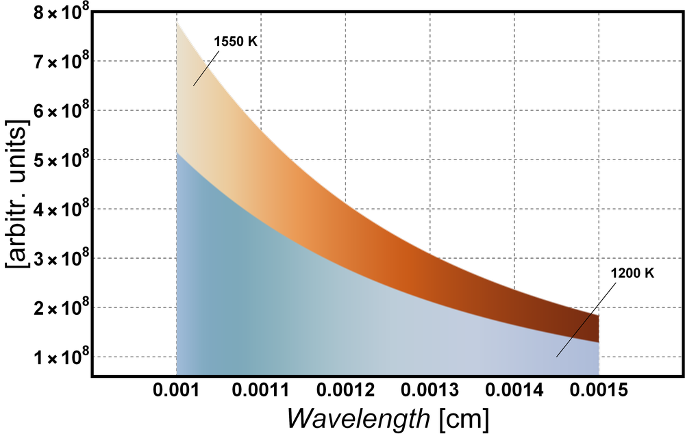
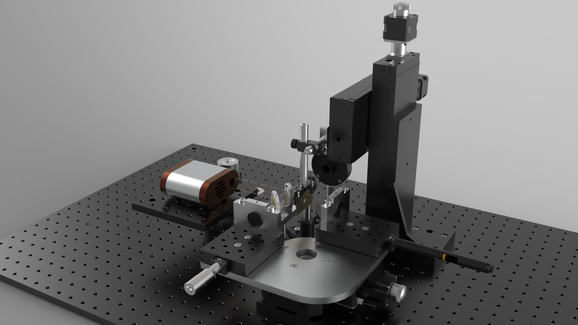
After the imaging results obtained for VIS radiation, the ones with terahertz (THz) radiation are presented here. The main differences in the experimental setup are the optical components, the radation source and the detector, as they cover the THz range. The images below are acquired with broadband radiation in the 20 - 30 THz spectral region, since the source emmitts a black body radiation at 1200 K (550 nm - 15 μm or 20 - 545 THz) and the single-pixel detector measures in the range 0.1 - 30 THz. The images appear slightly blurry due to the broadband imaging.
Scanning interferometry
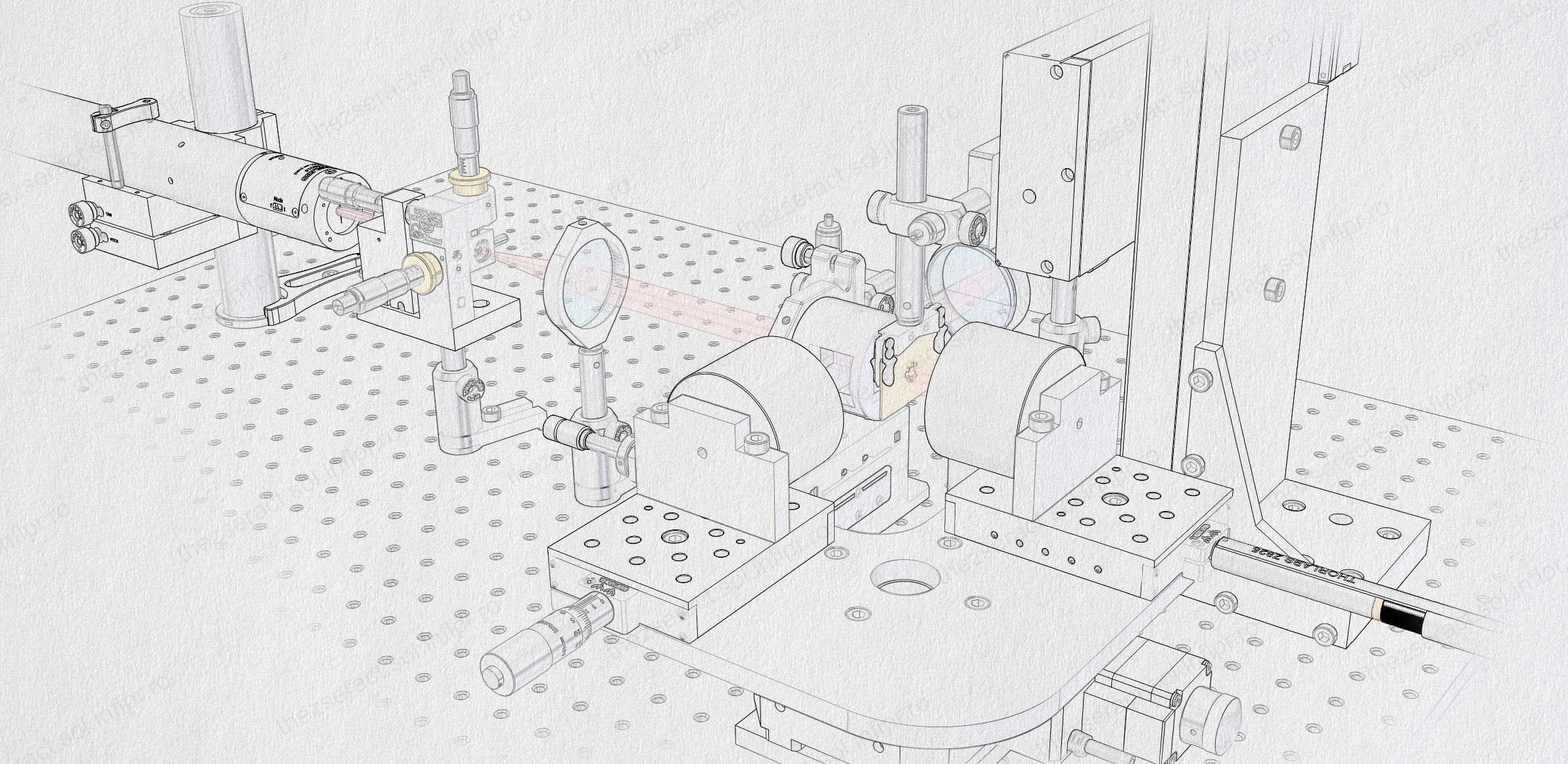
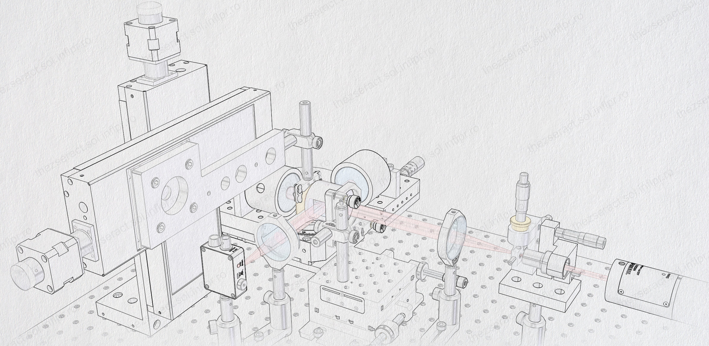
The term scanning interferometry means that localization of interference fringes during scanning of the optical path length (OPL) provides a way of measurement by controlled manipulation of the phase difference or optical path difference (OPD). Applications such as spectroscopy or profilometry are achieved by scanning of the interferogram or of the coherence of the input source, respectively. In this project, we designed and implemented both a visible and a terahertz experimental setup to measure the spectrum of the incident radiation or the profile of specific objects. These experimental arrangements are presented below. Depending on the measurement, the scanning is achieved by rotation of both mirrors around their point of intersection at a right angle or by translating one of the mirrors from the position of zero path difference (ZPD).
Development of functions - Fourier transform spectroscopy (FTS)
Fourier transform spectroscopy (FTS) is one application that involves scanning interferometry and single-pixel detection. The measurements imply scanning and recording the interferogram of the investigated source and, by Fourier transformation, extracting its spectrum. Depending on the necessary spectral resolution a number of 512, 1024, 2048, 4096, 8192, etc. should be acquired.
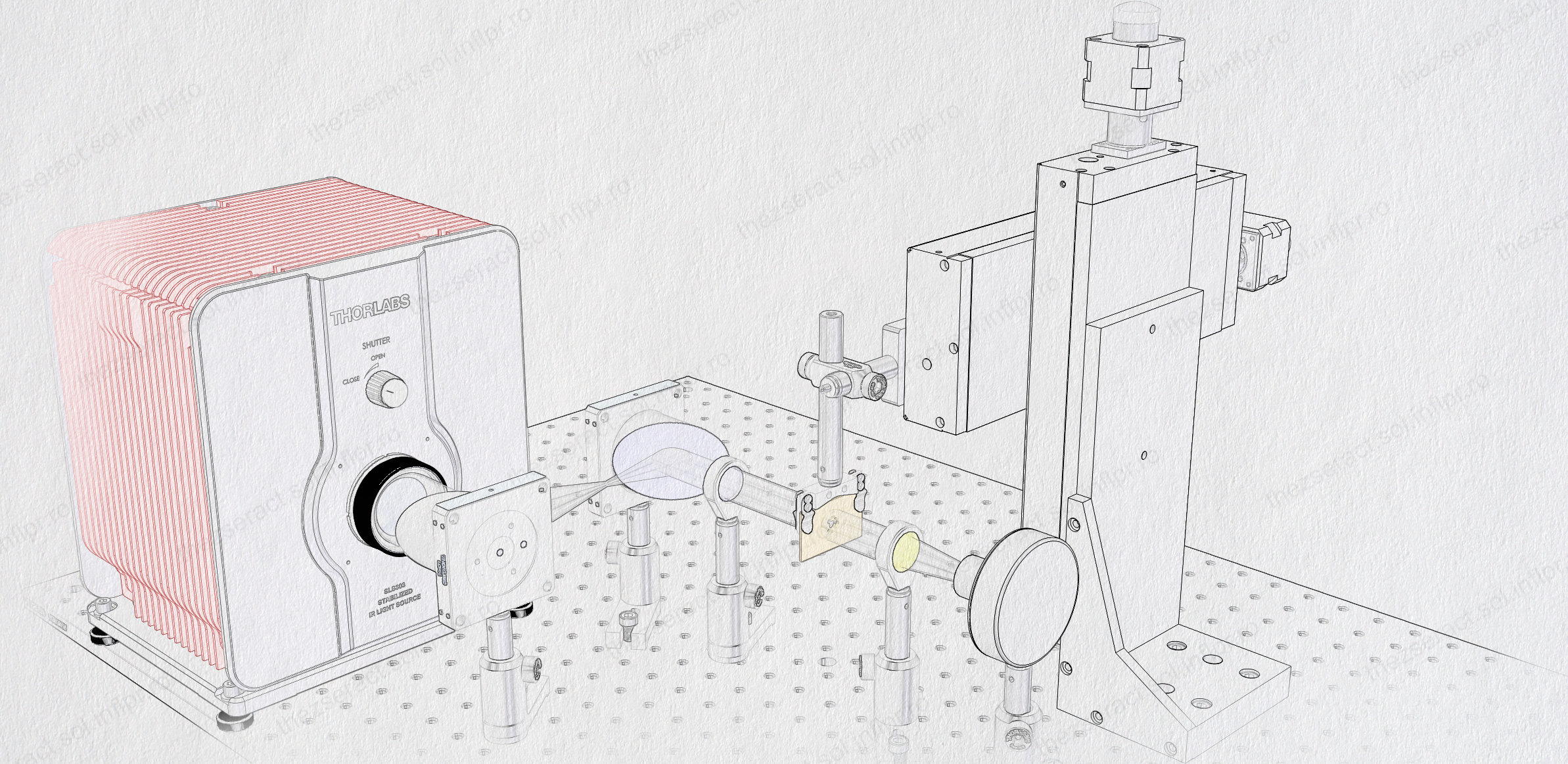
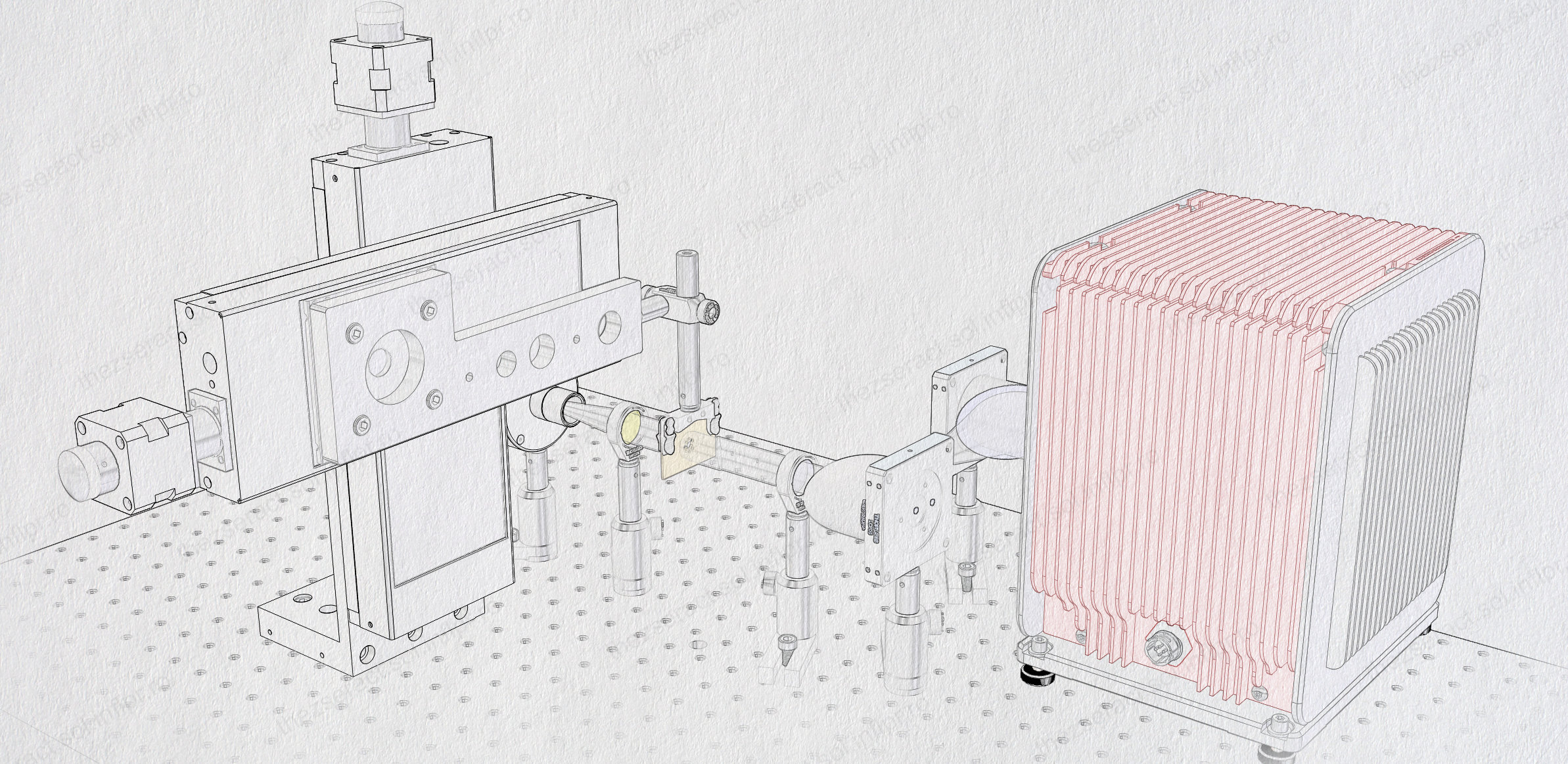
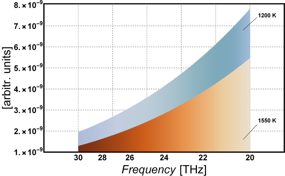
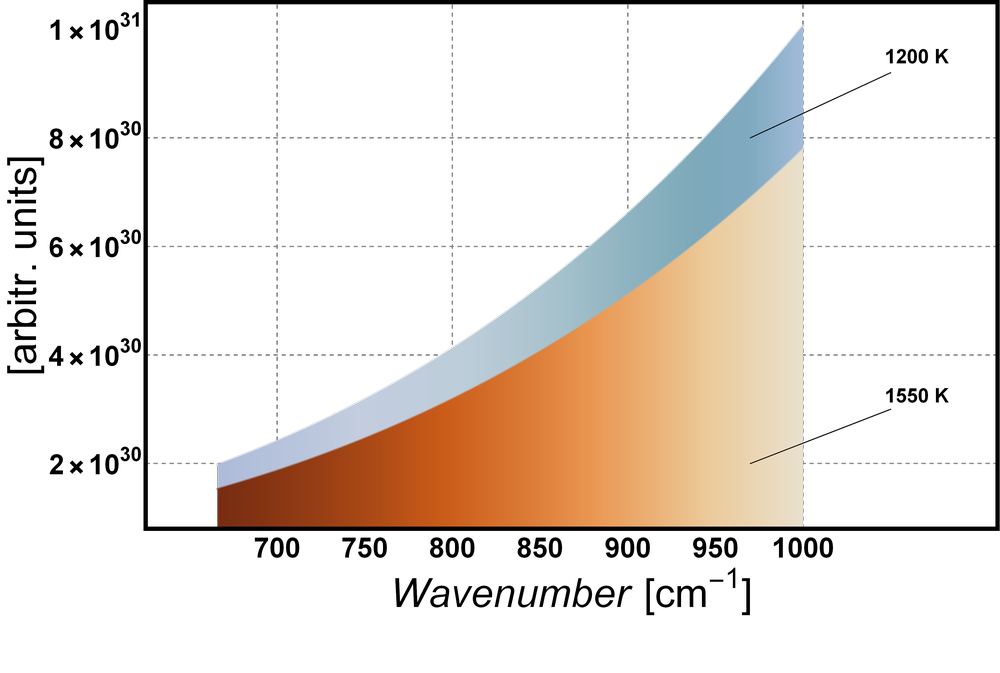
For this development function two black body radiation sources were used, namely a stabilized nitride globar ligh source (550 nm - 15 μm) from Thorlabs and the ARCLIGHT-MIR broadband lamp (1 - 25 μm) from Arcoptix. The spectra of these two sources are depicted bellow, together with the interest spectral range: 10 - 15 μm (20 - 30 THz).
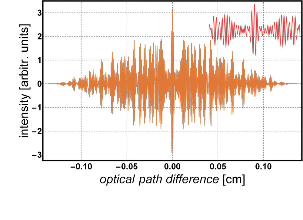
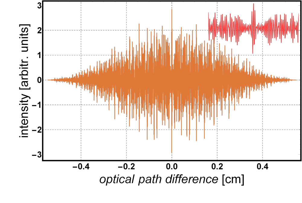
Bellow are a series of Haidinger interference systems, computed for two broadband sources, one emmitting in the range 10 - 15 μm (20 - 30 THz) and the other in the range 10 - 25 μm (12 - 30 THz), respectively. They are measured from 512, 2048 or 4096 data points, a distance d = 2.6 μm between the two interfering sources and using an imaging lens with f = 50 mm.
Practically, the interferogram data is acquired with a single-pixel detector by scanning via translation of the interferometer mirror. Thus, there will be an optical path difference (OPD) accumulation as a function of the intensity distribution that is recorded. The spectrum of the radiation source is obtained by applying the Fourier transformation to this recorded interferogram. Bellow are some examples in the interest spectral range for various number of data points. Note that the greater the number of data points the greater the OPD and the spectral resolution.
Development of functions - phase-shifting interferometry (PSI)
The second function that was developed within this project is phase-shifting interferometry (PSI) at THz frequencies. This implies changing the phase difference between the two interfering waves in a controlled manner by altering the distance between the two mirrors. Therefore, a scanning of the interferogram is also achieved. While in FTS the scanning is realized in very small steps, in PSI they are considerably larger. Also, the number of steps is, depending on the method used, much smaller in the case of PSI than FTS. The application developed with PSI is optical profilometry.
Using the 4-step phase-shifting interferometry method, the following computations were performed: the four phase-shifted Haidinger interference systems, wrapped phase, unwrapped phase, 3D profile and 2D profile. These simulations assume two plane mirrors in the interferometer (i.e., no object) and the following parameters: wavelength of 10.6μm, a distance of 2mm between sources and an imaging lens with the focal distance of 50mm.
The results for the same simulations as above are presented below but using a reflective object instead of the second mirror.
The same computations were performed using the 4-step method described above, but with straight equispaced interference fringes. This fringes are obtained by tilting one mirror at an angle around the vertical axis; this being a more reliable approach in profilometry measurements, given that straight and not curved surfaces are analyzed. These simulations assume a plane mirror and a reflective object in the interferometer; the following parameters were also used: wavelength of 10.6μm, 0.015 mrad angle between mirrors and an imaging lens with the focal distance of 50mm.
Following is another set of simulations using straight fringes with object and the following conditions: wavelength of 12μm and 0.02mrad angle between mirrors and an imaging lens with the focal distance of 50mm.
[2024] Stage III, the final phase of the project - Evaluation of the breadboard THz imaging interferometer
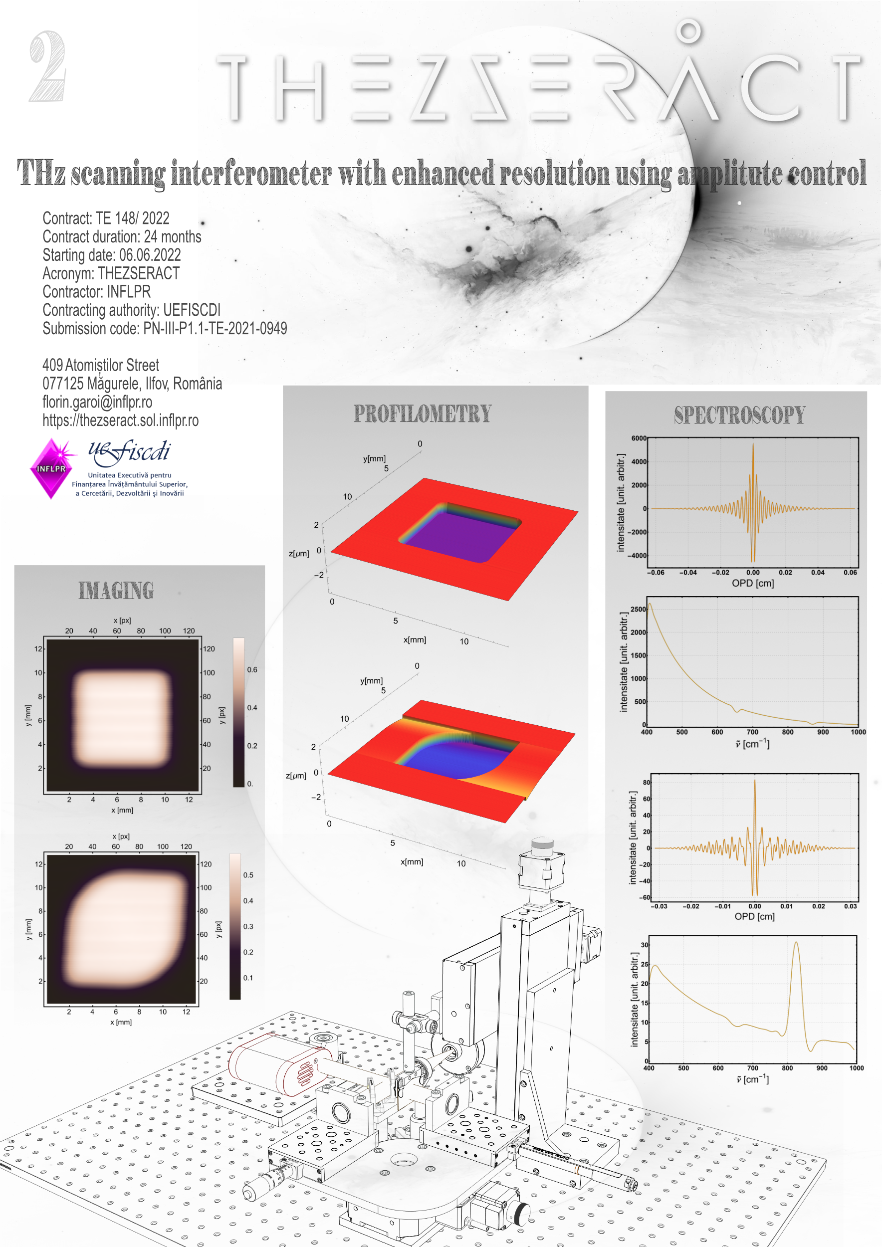
In the last stage of the THEZSERACT project, all three proposed modules of the scanning interferometer were realized and tested, namely: imaging, profilometry and spectroscopy. Two experimental arrangements, one for the visible range and the other for the THz range, were made and evaluated. The imaging module was evaluated by reconstructing several images (see the images below) of mask-type samples, both in the visible range (using the radiation from a HeNe laser @ 632.8 nm) and in the THz range (using a Arclight-MIR-20 @ 1-25 μm radiation source from ArcOptix).
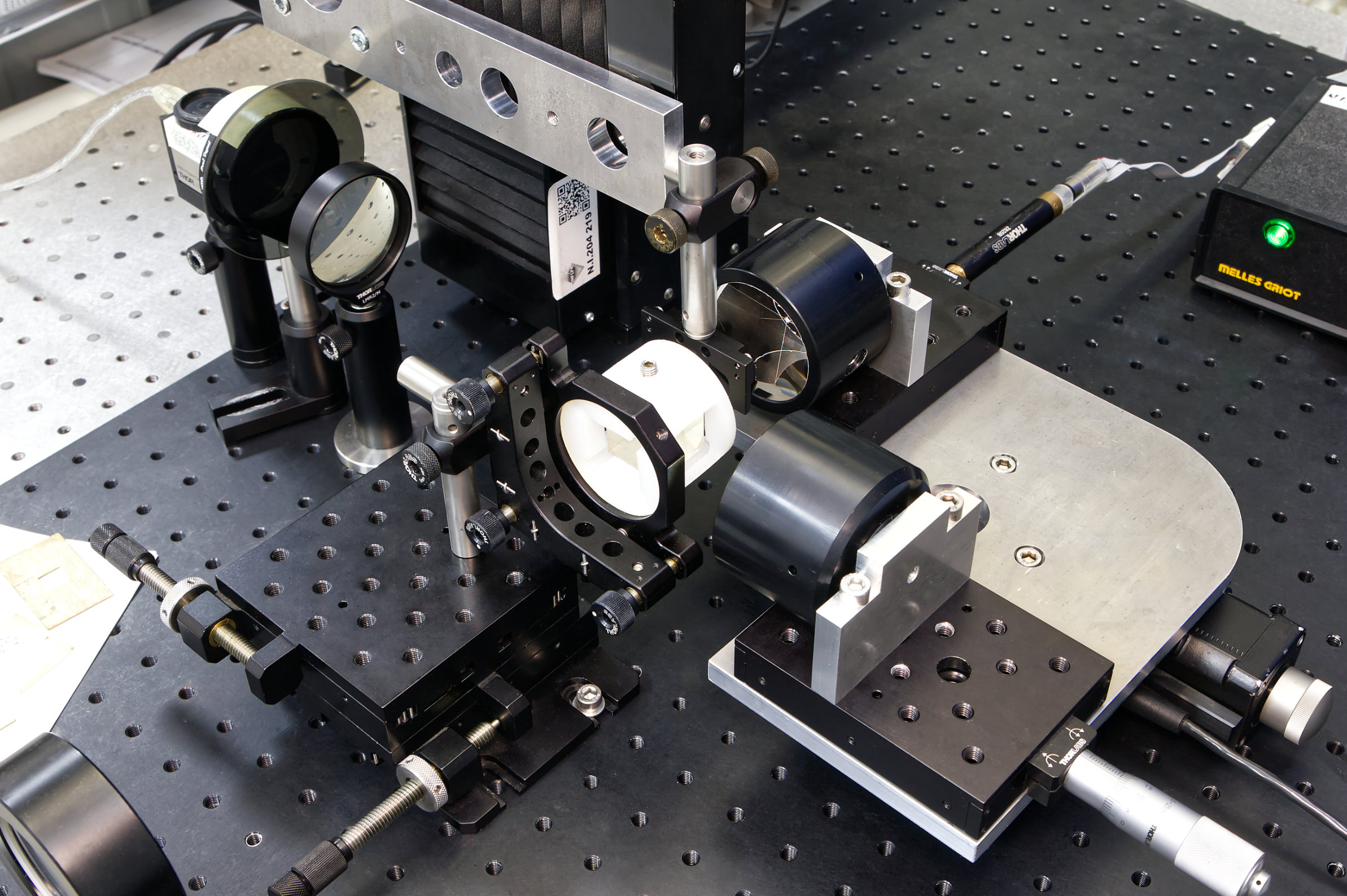
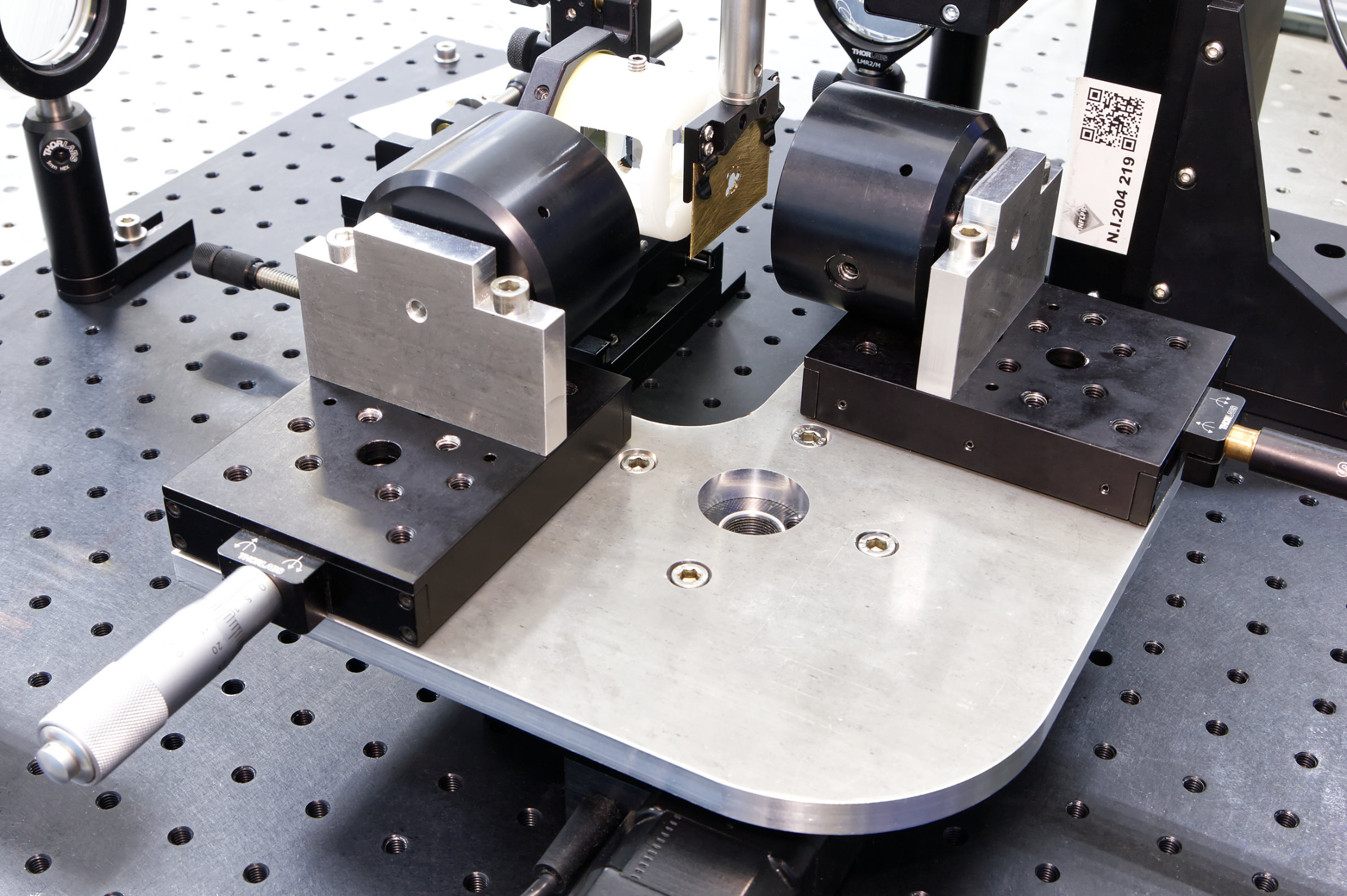
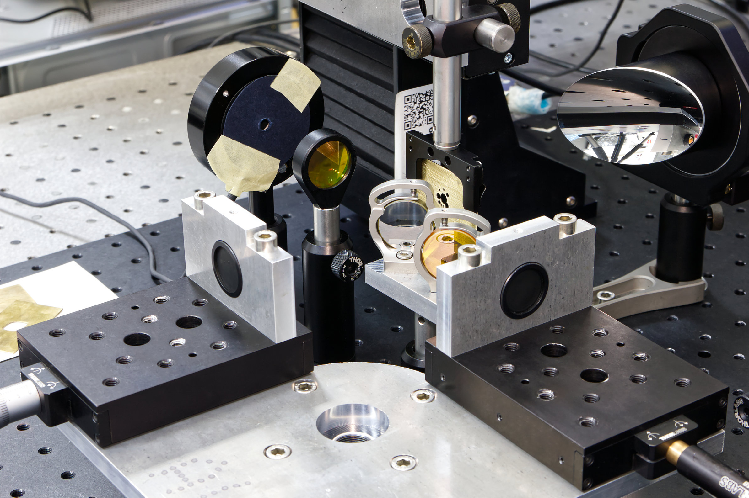
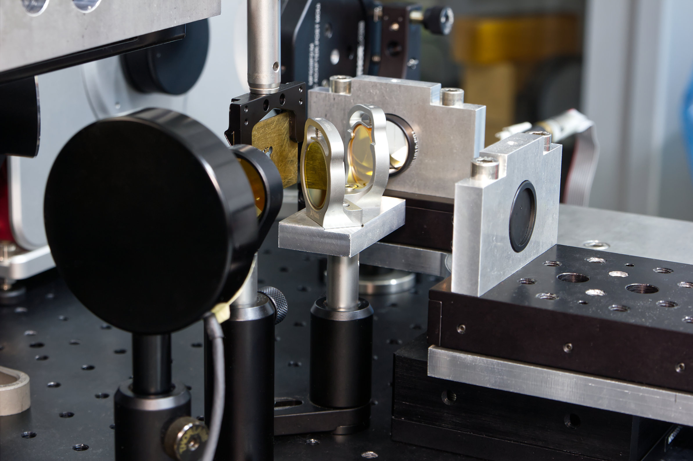
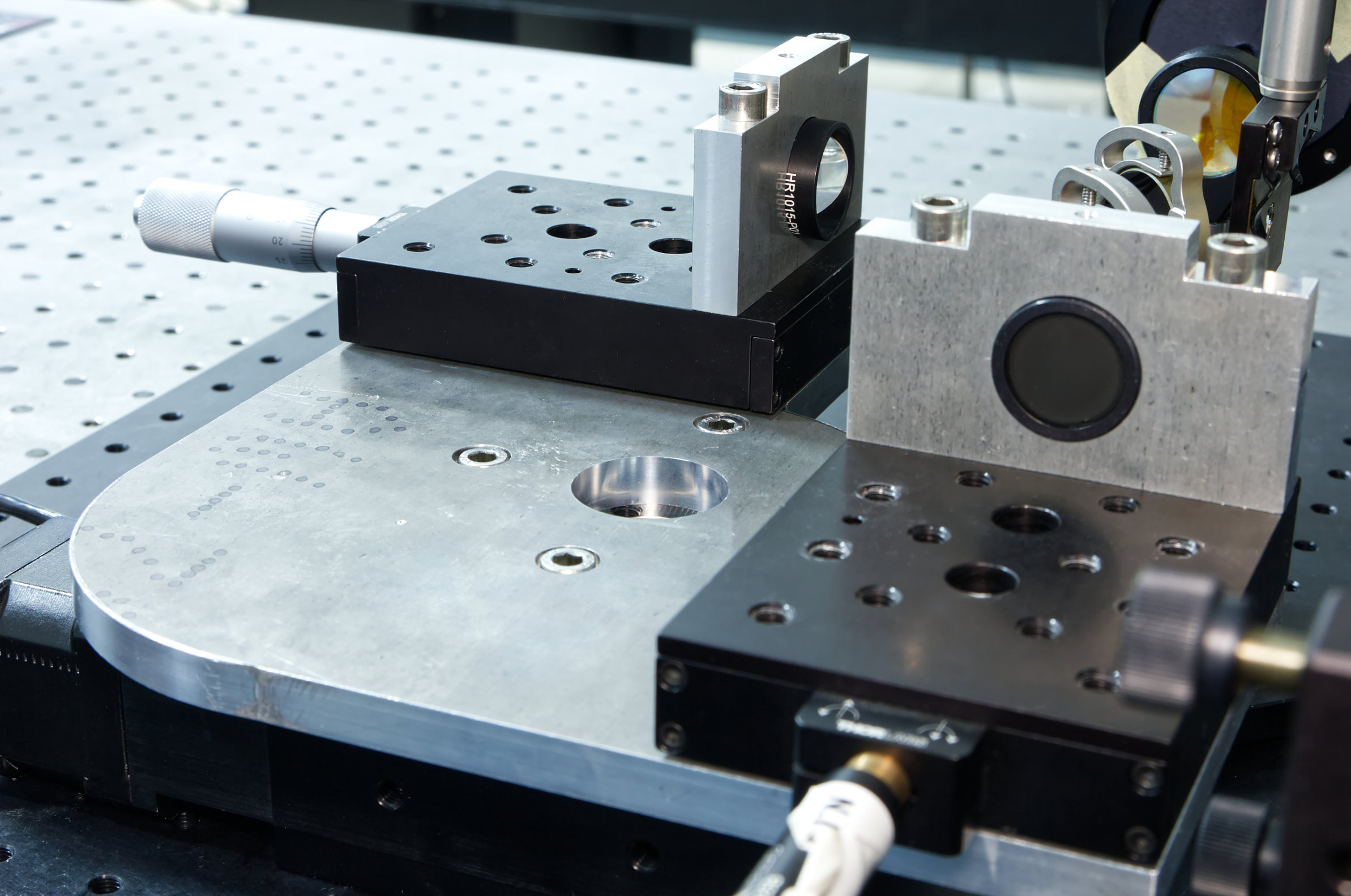
To evaluate the profilometry and spectroscopy functions, two scanning interferometers were designed and built, one for the visible range and the other for the terahertz range. They were designed on the principle of the permanently aligned interferometer (IAP), in the form of an aluminum monolith on which the interferometer mirrors are placed. Thus, the retroreflectors/ mirrors are fixed on the interferometer plate, and the phase shifts can be in troduced by rotating the interferometer plate or by translating one of the retroreflector along the optical axis. As a result, the optical path difference (OPD) between the retroreflectors and the beamsplitter cube can be controlled. These two scanning interferometers are presented in the following images.
The profilometry function was evaluated by measuring the 3D profiles of reflective samples with a nominal height of 1 µm, using two LEDs – with central wavelengths of 530 nm (green) and 590 nm (amber) respectively – as visible radiation sources and the pump laser of the FIRL-100 system (at 10.6 µm wavelength) for the THz range. The four-step phase shift method was also used consisting of π/2 [rad] successive phase shifts between the four recorded interferograms. This was achieved by implementing λ/8 [m] displacements of one of the mirrors or rotations of the IAP interferometer with a value of arcsin(25 λ/8) [rad], given that the radius of the IAP is 80 mm. Some of the reconstructed profiles, both with the two wavelengths (for VIS measurements) and one wavelength (for THz measurements) method, are presented below. They are profiles of reflective samples with various shapes but the same nominal step height of 1 µm.
The spectroscopy function was evaluated by calculating the optimal parameters of Fourier transform spectroscopy (FTS) for the infrared (IR), terahertz (THz) and visible (VIS) spectral domains, but also by measuring some emission spectra in the available THz spectral domain, i.e. 10 – 25 μm (12 – 30 THz/ 400 – 1000 cm-1). With FTS technique the interferogram of the incident radiation source is swept discretely with a certain increment and the data for each scan is recorded in the form of I(OPD). Then, by applying the Fourier transform to this interferogram, the spectrum of the incident radiation is obtained. It has been shown that the implementation of FTS in the THz domain can be done following the technology already established in the IR domain, with slightly better results in terms of spectral resolution. Following are some results for both the measured spectral domain, given by the available radiation source, and with a bandpass filter @ 12 μm central wavelength, applied to that spectral domain.
References
Resources
Contact us
National Institute for Laser, Plasma and Radiation Physics (INFLPR)/ Laser Department Atomiştilor 409, PO Box MG-36 Măgurele 077125, Ilfov, România Telephone: +40 21 4574489, Fax: +40 21 4574243
